Overview of Single Line System
The single-line system is suitable for equipment where lubrication points are concentrated within a certain range, as well as for small to medium-sized machinery. The progressive operation system ensures reliable lubrication and allows precise adjustment of the lubrication amount for each lubrication point.
Features
①The piping from the pump to the distribution valve consists of one pipe line.
②If even one point becomes blocked, the distribution valve piston will not operate, causing the main pressure to rise and alerting to abnormalities, thereby ensuring reliable lubrication delivery to all points.
③By selecting the distribution valve piston, the supply amount of lubricant can be finely adjusted for each lubrication point.
【Note】
When designing the system, the piston size for all distribution valves must be selected. Therefore, if the number of lubrication points increases or decreases, the entire system configuration needs to be reviewed.
Manual pump system
The most simple and cost-effective method using a manual pump, enabling centralized lubrication for around 100 points with just the operation of the handle.
| Pump | ①Manual pump |
|---|---|
| Distribution valve | ②KL, KM type ③KM, KJ type |
| Diagram | 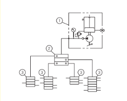 |
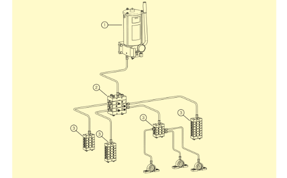
Electric pump
An automatic centralized lubrication system using an electric pump and an electrical control panel.
| Pump | ①Electric pump |
|---|---|
| Distribution valve with cycle switch | ②KL, KM type |
| Distribution valve | ③KL, KM type ④KM, KJ type |
| Electric control panel | For KEPS-□-SO |
| Diagram | 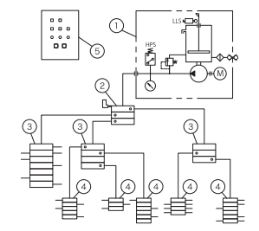 |
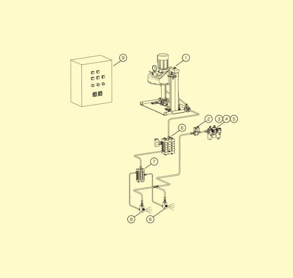
Pneumatic Pump method
Automatic lubrication system with a compressed air-driven pump and an electrical control panel.
Without the electrical control panel, the pump will be operated and stopped manually. However, by replacing the solenoid valve with a manual valve, it can be used in explosion-proof areas.
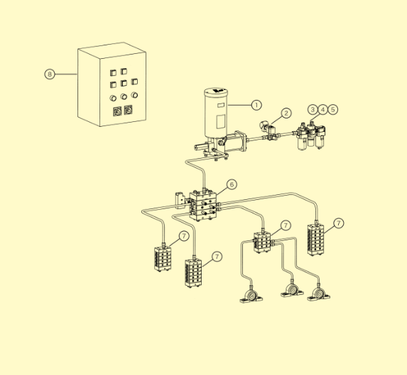
| Pump | ①Pneumatic Pump |
|---|---|
| Air equipment | ②Solenoid valve ③Filter ④Regulator ⑤Lubricator |
| Distribution valve with cycle switch | ⑥KL, KM type |
| Distribution valve | ⑦KM, KJ type |
| Electric control panel | ⑧For Pnuematic pump |
| Diagram | 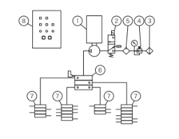 |
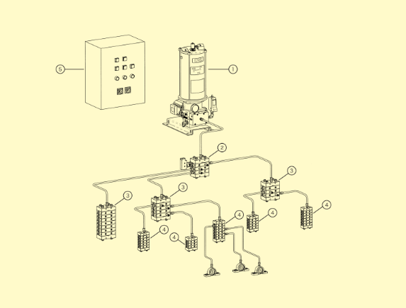
Multi-zone method
One pump can deliver lubricant to multiple zones, which is ideal for large-scale equipment. The central pump is equipped with a high-capacity drum-mounted pump, and with solenoid valves installed for each zone, lubrication can be provided to specific zones and timing.
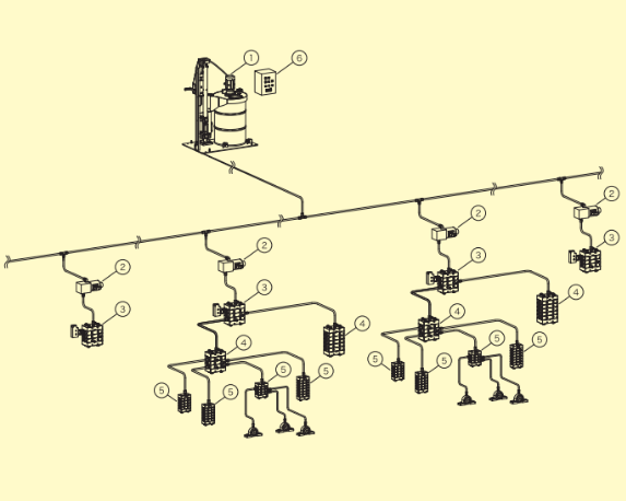
| Pump | ①Electric pump |
|---|---|
| Solenoid valve | ②Two-way solenoid valve |
| Distribution valve with cycle switch | ③KL, KM type |
| Distribution valve | ④KL, KM type |
| Distribution valve | ⑦KM, KJ type |
| Distribution valve | ⑤KM, KJ type |
| Electric control panel | ⑥For KSPN1000 |
| Diagram | 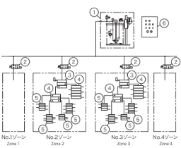 |
Spray method
It sprays grease or oil onto open gears, chains, and similar components in desired amounts and at specified timings.
| Pump | ①Electric pump |
|---|---|
| Air equipment | ②Solenoid valve ③Filter ④Regulator ⑤Lubricator |
| Distribution valve with cycle switch | ⑥KL, KM type |
| Distribution valve | ④KL, KM type |
| Distribution valve | ⑦KM, KJ type/td> |
| Spray valve | ⑧KP-0, KP-2 |
| Electric control panel | ⑨Spray for KSP820 |
| Diagram | 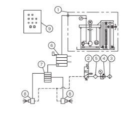 |
Grease Gun method
Grease is supplied directly to the distribution valve using a gun, allowing centralized lubrication for approximately 2 to 16 points. The amount of lubrication can be visually checked with the cycle rod on the distribution valve.
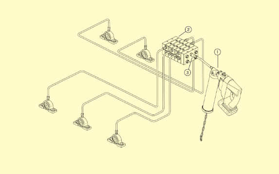
| Pump | ①Grease Gun |
|---|---|
| Distribution valve | ②KL, KM, KJ type |
| Distribution valve with cycle switch | ⑥KL, KM type |
| Fittings | ③Grease Nipple |
| Diagram | 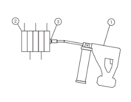 |
PDF files of catalogues are available.